SketchUp: Modeling Table and Stool Legs with Rake and Splay
Correctly modeling angled legs in SketchUp requires the right techniqueLegs set at an angle other than vertical is a common feature of stools, chairs, and some tables. Christian Becksvoort’s Sturdy Stool is a good example as well as the typical Windsor chair. Garrett Hack has done some lovely small tables with legs that have fully tapered raked and splayed legs such as his Fir and Cherry Side Table.
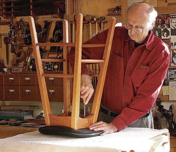
Christian Becksvoort’s Sturdy Stool
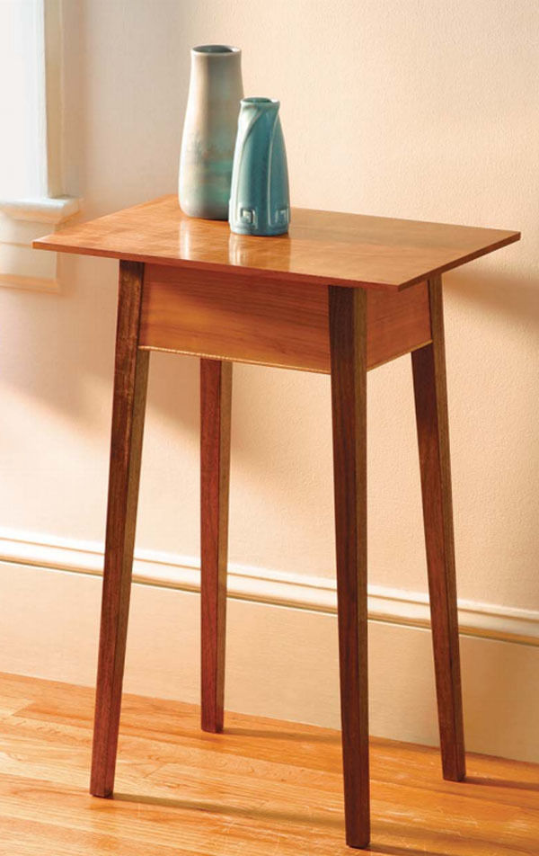
A small table by Garrett Hack
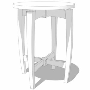
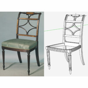
Correctly modeling legs like these in SketchUp requires the right technique. One easy way to get it right is through the use of an extension called, appropriately, Rake and Splay. I used it when I drew the plans for Becksvoort’s stool and Hack’s small side tables. I also used it recently when I created the SketchUp model of this table based on on made in Poland during the early 1950’s.
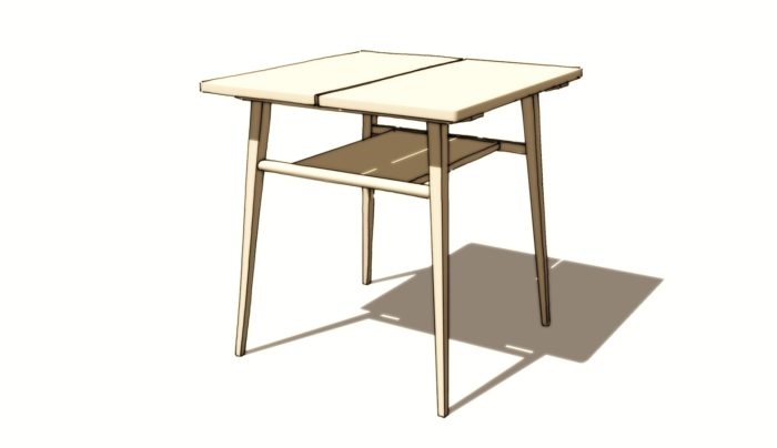
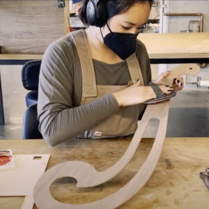
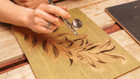
The video shows how to use this hand tool to get the legs drawn correctly. After getting the leg in the right place, I also show how to cut the top and bottom parallel to the floor. Maybe you can find some useful for the extension, too.
–Dave






Comments
Just installed Rake and Splay. Thanks!
Dave,
I was not aware there is a flip along component and a separate flip along model axis direction. I usually just use the context flip and it works for my needs.
In this blog post video at 12:42 you had the single leg component and added an additional line, selected the leg and the line, move/copied both, then did a flip along red direction (not a flip along components red) Was this required because the leg is tapered on four sides ? I ask because for the Becksvoort stool Leg (in previous blog post on June 7, 2015 at time 7:24), for the same step of copying the leg, you were able use flip along components red. Can you please explain the difference between the "flip along" of the two leg types ?
Thank you.
There are actually nine different Flip Along commands. There are three for flipping along the local/model axis directions which apply to multiple selections such as a bunch of loose geometry or as in my example here, a component and a single edge. Then there are the three for flipping a single component about its axes and there are three for flipping a group along its axes. The commands that show in the Context menu depend on the context--what you have selected.
For this table the leg component was created so the bounding box is aligned with the geometry and the leg component is rotated to the rake and splay angles. If I had flipped just the component, my flip along choice would have been relative to the leg component's axes which would put the leg in the wrong orientation. By adding something else to the selection, I could flip along the model axis direction. Once the second leg is correctly oriented, the two legs can be copied and flipped, again along the model axis direction because there's more than one object selected.
In the case of the Becksvoort stool, I waited to make the leg component until after I had set the rake and splay angle for the geometry. In that case the component's axes were still aligned with the model axes and flipping along the component's axis directions results in the desired orientation. I did have to go back later and change the component's axis orientation to suit the geometry, though.
Basically two different routes to the same end.
-Dave
Thanks so much Dave for the clear explanation. I'll remember the differences for future modeling. I don't recall seeing this explained before so hopefully others that read this will also benefit.
Log in or create an account to post a comment.
Sign up Log in