How to Create Kumiko at the Table Saw
Smart jigs simplify this complex design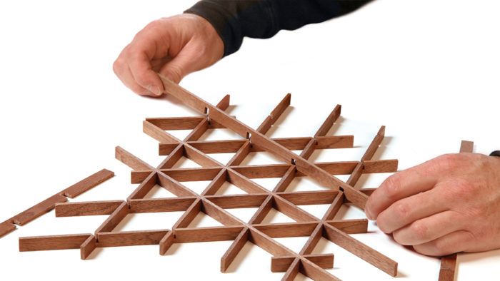
Synopsis: Captivated by Japanese kumiko latticework but looking for a simpler way to accomplish it? Mike Farrington has solved that puzzle with a tablesaw sled that makes the complex, interconnecting joinery quick and repeatable. Paired with a couple of planing jigs, this technique will put kumiko within your reach quickly, and after trying it a few times, you will be hooked.
I was first captivated by Japanese kumiko latticework on the back cover of FWW #226, which featured a stunning cabinet by John Reed Fox. Fox’s piece had a pattern known as asa-no-ha, based on a square grid with 90° lap joints. (Michael Pekovich covered the how-to for that pattern in a Master Class in FWW #259.) After figuring out the square design, I explored others and found that many of my favorites are built on a grid of equilateral triangles.
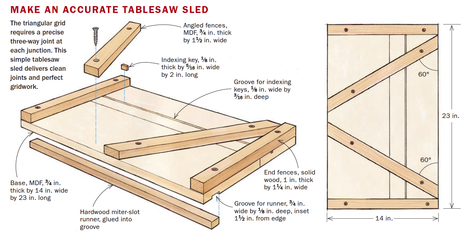
While triangular gridwork is more challenging to produce than a 90° lattice, I developed a simple tablesaw sled that makes the complex joints quick and repeatable. I also use a planing jig so that each strip will have a uniform thickness—especially important with this three-way joinery. The infill pieces are more straightforward, made easy by a couple of planing jigs very similar to those Pekovich uses. Using this approach, you’ll produce gridwork and infill so clean and snug that it doesn’t need glue (though I do use a tiny bit). The kumiko process is fun and fulfilling, which is probably why the craft has survived for centuries. There still is a learning curve. Don’t give up. Your first attempt will be rough, the second will be better, and by the third you’ll have nailed it.
A word about design and wood
The foundation of any kumiko pattern is the gridwork, which can be scaled to suit everything from large shoji screens down to door panels, lamp shades, and coasters.
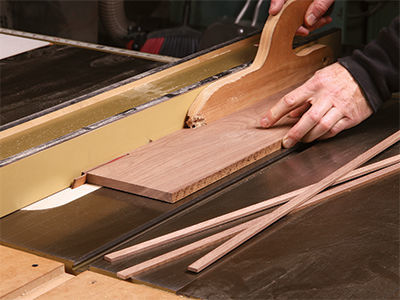
The main variable is the pitch, which is the distance between the lap joints. A pitch of 2 in. to 3 in. is a good starting point for most projects. Another variable is the thickness of the strips, which is tied directly to the kerf of the sawblade used to make the three-way joints. Blades that are full-kerf (1/8 in.) and thin-kerf (typically 3/32 in.) both work great. For larger patterns, you might choose a two-blade stack, or a thick blade made for joinery. As for the width of the strips, 1/2 in. is a good rule of thumb.
Kumiko looks best with woods that are lighter in color with straight grain. Quartersawn or riftsawn material is best, with tight, subtle grain. I often use maple, but I’ve had success with fir, alder, walnut, and cedar, too.
 From Fine Woodworking #274
To view the entire article, please click the View PDF button below.
More on Finewoodworking.com:
- Spice Up Your Work with Kumiko by Michael Pekovich #259–Jan/Feb 2017 Issue
- The Quiet Art of Kumiko by Michael Pekovich #259–Jan/Feb 2017 Issue
- Masters of The Craft: John Reed Fox
Fine Woodworking Recommended Products
Whiteside 9500 Solid Brass Router Inlay Router Bit Set

Bahco 6-Inch Card Scraper








Comments
So much for the "Quiet Art of Kumiko"!
This method leaves a void in the joint that gets covered up. To make a solid joint, cut the middle and bottom pcs as described but one of the cuts on the top pc only needs to go ⅓’rd of the way through (double check which of the two cuts should be the shallow one before cutting!).
Having failed on three occasions to produce an acceptable mitsukude joint manually, this jig worked for me first time. So, thanks to Mike Farrington, although it does make me fell a bit of a fraud and I will get back to trying to do it with hand tools. One improvement to Mike's jig:- I ran a 2¼" strip of clear polycarbonate from the front square fence most of the way towards the back, so as to leave just enough room to use a depth gauge to set the depth of cut. Not ideal but more effective than red paint.
Thank you so much for putting this together. I'll finally be able to produce enough kumiko to make it cost effective. It's so beautiful. People love it but I haven't been able to use it for the time it takes to make. Thank You!
This is one of the most frustrating FWW articles I can recall reading. The drawings give no indication of direction -- which end of the sled faces the user and which slide the groove for the key goes. The only way to know is to consult the photo on the bottom of page 69. But that has details that the drawings leave out! Most importantly, the operator is shown making a cut on the far side of the far fence. But the angled fence goes against the sled fence, giving the operator no way to advance the stock beyond a cut or two.
In the photo this appears to have been solved by moving the fence forward on the sled, but that's not what the drawings show.
There are inconsistencies that don't matter as much -- the photographed sled has its fences attached from below; the drawings from above -- but why not draw the actual project with clear indications of its orientation?
Shoddy work FWW, shoddy work.
Log in or create an account to post a comment.
Sign up Log in