Modeling Continuous Curves Across Parts in SketchUp
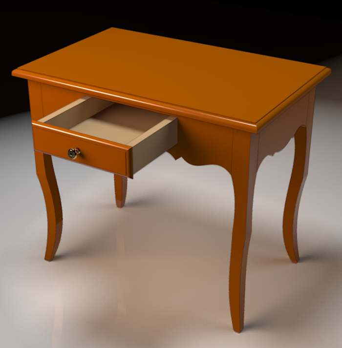
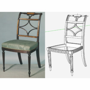
Creating this continuous curve in the shop is fairly straightforward. Assemble the parts and fair the curve. In SketchUp it's a little different.It’s not unusual in furniture design to have curves that run continuously across different parts. You can see this in furniture such as a Bombé dresser or this Louisiana Creole Table designed by Greg Arceneaux.
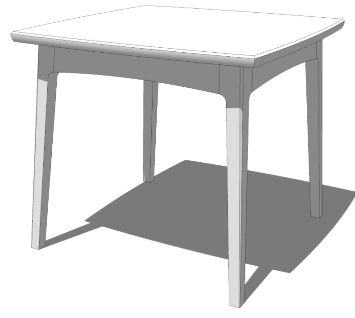
Creating this continuous curve in the shop is fairly straightforward. Assemble the parts and fair the curve. In SketchUp it’s a little different, though. Well, at least it is if you’ve used separate components for each of the parts. I had to do this recently when I created the model of Philip Morley’s Modern Dining Table for the plans. The process isn’t very difficult and it can be made easier with a few shortcuts.
The same basic process can also be used to transfer geometry from one component to another. In this video I’ll show you how to do both of these things.
This is done with native tools although I used a couple of extensions when I drew the curves for the leg and apron. Those extensions are Bezier Spline and TIG-Weld which are both available from Sketchucation. There are several other extensions that could be used for these operations, too.
I hope you can find something useful to take away from this.
–Dave






Comments
Can you please explain the use of "orient faces" in the demo?
Hi Joe,
Thank you for asking that question. I did just gloss over it and probably shouldn't have.
Faces in SketchUp have fronts and backs. With the default templates front faces are displayed as white and back faces are displayed with a blue gray color. (I've edited my default template style so that the back face color is green. The displays on some computers I use make it difficult to discern which faces are reversed and which are simply shaded. The green color makes that much easier to see.)
A 3D volume should have have only the front white faces exposed. All of the back faces should be on the inside of the volume and only white front faces should be seen. In the video, the geometry of the tenon on the apron has the correct orientation. When that tenon geometry is pasted into the leg, it still has the same face orientation but that means for the mortise, those faces are inside out. To fix the reversed faces you can either select the reversed ones, right click on them and choose Reverse Faces or, as I did in this case, right click on a correctly oriented face and choose Orient Faces. This is easier when there are a number of faces to fix.
Proper face orientation is part of keeping the model clean. There are a number of reasons for keeping face orientations correct. The action of some tools, such as Push/Pull is affected by which side of a face you are clicking on. If you are adding materials to your model face orientation affects the way they are applied. Some rendering applications won't render back faces even if they have textures applied to them. They end up looking black. Not like painted black, but black like there's absolutely nothing there. And for 3D printing face orientation is used to tell the printer which side of the face has the printing material and which is room air.
Clean models are easier to work on and it's easier if you clean up as you go. Keeping face orientation on 3D volumes is just part of that.
-Dave
Thank you for such a detailed reply. I try to clean up as I go, but there's usually at least one seemigly minor artifact where anything I try just breaks the model. I think I can now fix one or two of those. Until now, I didn't even understand the issue, let alone the fix.
You're quite welcome Joe. If you run into something that seems to break your model, let me know. I could take a look at it and maybe give you some ideas about how to fix it or better, prevent the problem.
-Dave
“[Deleted]”
Hi Dave,
How did you create the 1" radius that connected the two curves and maintain tangency to the curves? That's not easy to do with the native tools, so I assume you used an extension (or some cool trick).
Hi Carl,
No extensions were harmed in the making of that one inch radius. I drew the curve on the bottom of the apron first and then drew a circle 1 in. below the end of the curve. I used a guideline parallel to the last segment in the apron curve placed one in. below the apron and a perpendicular guideline of the end of the curve to identify the center of the circle. I used a circle with 48 sides. As for the curve on the leg. I start that at the foot and then found the vertex on the circle that created a tangent. Sometimes that takes a little trial and error to figure out which vertex to anchor the curve to but you can place the point at one of them and test it. If you aren't happy with appearance, hitting Esc will disconnect the curve and you can pick a different vertex.
-Dave
Log in or create an account to post a comment.
Sign up Log in