Adding phantom lines in SketchUp
SketchUp makes it easy to explain technical details, including a way to show phantom lines demonstrating how pieces connectI recently made a online Zoom presentation of my Timber Frame project in the back yard. The timber frame joinery is similar to furniture but also unique, and I wanted a way of showing the differences. SketchUp makes it easier to explain the technical details, including a way to show Phantom Lines. I’ve provided a video below on how I created the diagram with Phantom Lines.
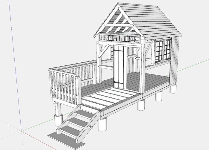
Here is an assembly view of the Timber Frame project.
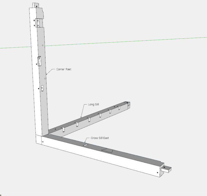
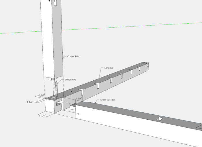
I picked one of the typical joints where the Post meets the Sills.
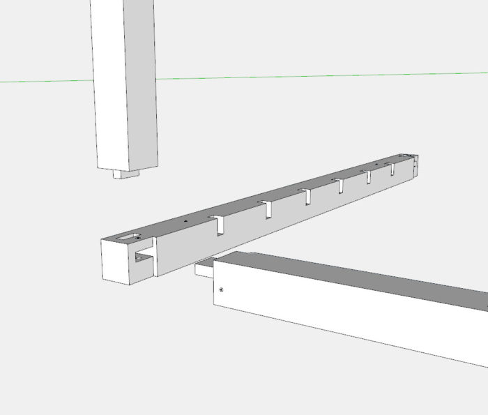
I “exploded” the three components but without phantom lines, it’s harder to see how they all connect.
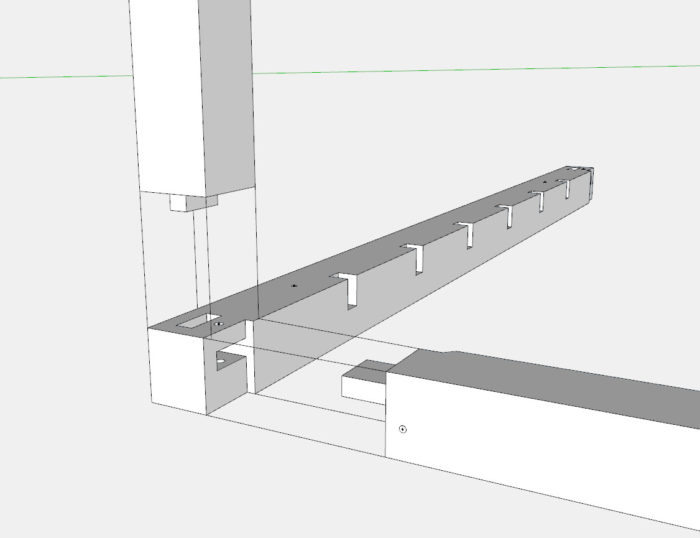
You can show solid lines indicating how the pieces connect, but this is not ideal…..
In SketchUp, you can change these solid lines to several other representations, by using a different Tag (used to be called Layer). In the picture below, you can see the Tag Phantom Line in the Default Tray. To create a new Tag, you click on the + button, then click on the word Default. A box appears showing various options for the line style. I chose the style showing a long dash, then two shorter dashes.
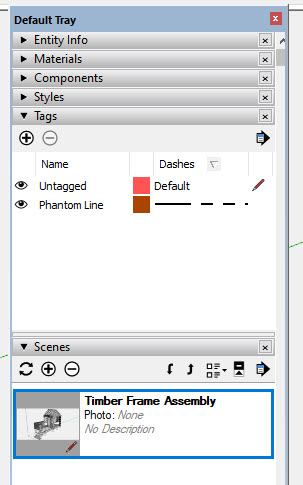
After creating the Tag, you use the Line Tool to create the Phantom Line, then change that line’s Tag from Default to the Phantom Line Tag using the Tag Tool Bar. It is easier to see these actions in the video below.
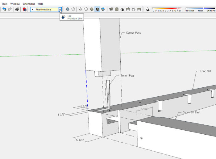
Here is the final illustration I used in the presentation.
Tim
KillenWOOD.com







Comments
Thanks for the tutorial. I knew this feature existed, but I never took the time to try it. I am working on a Layout project now and this helped.
It's important to note that the same old rules apply from the days of layers regarding tag usage. All edges and faces should be created and left untagged. They should be grouped (or componented) and only the groups/components get tagged.
Log in or create an account to post a comment.
Sign up Log in