Testing a tambour design
SketchUp is an efficient way to work out the design of the grooves and tambour slats in a 19th-century writing desk.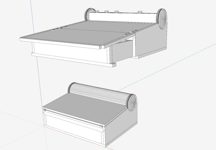
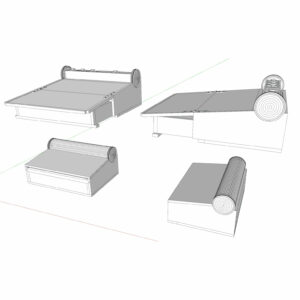
I’m reproducing a portable writing desk of 1810 originally built by the Seymours in Boston. There are several versions of these desks, and the one I’m working on is shown at Winterthur Museum. Here are two views of my SketchUp design, one of the desk in the closed position and another in the open position.
The tambour in the lower assembly is made up of 56 3/16-in. by 3/16-in. slats glued to a canvas backing. When the desk is closed, the tambour covers the container in the rear of the assembly. Since the tambour is connected to the back of the drawer, its position is based on drawer location. When the drawer is withdrawn, the tambour exposes the rear container where pencils, pens, ink, etc. are located.
I used SketchUp to work out the design of the grooves and tambour slats. After “hiding” some of the side components, you can see below the inside of the desk and the position of the tambour in the closed position. I wanted to make sure that the tambour slats would run efficiently throughout the grooved path in the desk sides and turrets.
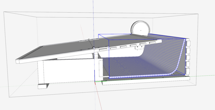
I attached a video of my process of placing tambour slats within the grooves and thus verifying a smooth working movement of the tambour.
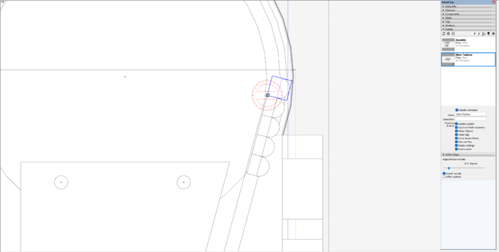
Here is a view showing my copying of a slat. In the current position, this new slat collides with the side of the groove. It must be rotated to clear the interference.
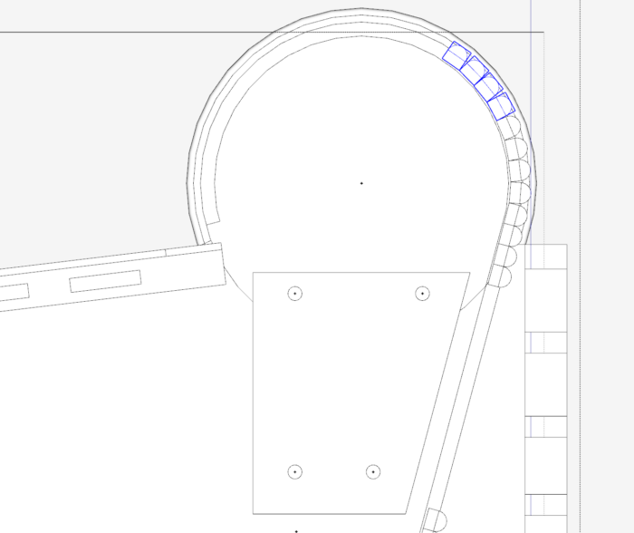
After adding and rotating a couple of slats, I am able to copy multiple slats by rotating the group from the centerpoint of the groove. This view shows copying four at a time. The next copy can be eight in one go. So the copying works quite rapidly.
Here is the video…..
More from Tim Killen
 |
Displaying alternatives in SketchUp and Layout |
 |
Dovetailed drawer design in SketchUp |
 |
Creating a cutaway view in SketchUp |
Fine Woodworking Recommended Products
Dividers
Drafting Tools
Circle Guide







Comments
rather than copy, rotating one, then two, then four - just make the original, then select it, activate the rotate tool, hit control (for copy), then rotate about the center like you did. Then type "x10" in the measurements box and you'll get all the copies you need. Obviously you might want to use a value other than 10.
While this is a good way to get a good starting point to size the slats (or the groove), my experience is that you'd better make test pieces to confirm the fit before proceeding with the actual project parts.
I believe your suggestion won't work, as each slat has a unique rotation about its own center. There's the individual slat rotation, then the additional rotation about the Turret center.
By having the detail in SketchUp showing the clearance of the slats to the groove, I was confident that it would work. I did not make test pieces to confirm the fit. I was careful to make the slats and their end rabbets exactly to dimension as in the SketchUp design. I always had the option to shave to fit, but this was not necessary.
Tim
Part of the reason you probably feel the need to tweak each slat model individually is because your model of the circular track has a low facet count - we can see the faceting even in the images in the post. The facets are slightly wider than individual slats so you get a weird periodicity of the desired rotations. If you end up cutting this track as a true circle using a compass jig for your router, then the ideal orientation of the slats is with the flat (interior) side perpendicular to the line through the center. This is what you get by orienting the first modeled slat perpendicular, then rotating about the center.
Log in or create an account to post a comment.
Sign up Log in