Hi all,
This may have been answered before, but I’ve searched, and I can’t find it.
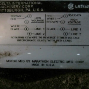
I need to convert my Delta 14″ bandsaw from 115v to 230v. The wiring diagram is on the motor, so it should be easy – but try as I might, I can’t see how the diagram relates to the actual wiring. This is the diagram:
and this is the info plate with details of the motor:
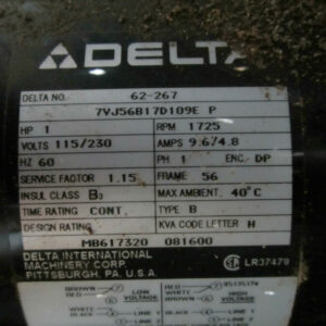
The wiring looks like this:
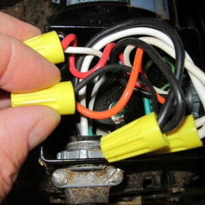
… and to make it clearer, I’ve traced it and drawn a natty diagram:
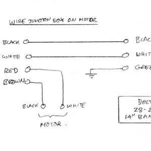
So… Firstly, the present wiring, which I used to use on a 115v supply, and has a standard 115v power plug, doesn’t actually resemble either the ‘Low Voltage’ or the ‘High Voltage’ diagram on the motor plate.
Secondly, the red and brown switched power aren’t connected together, as in the ‘Low Voltage’ diagram.
I’m hoping that one of you kind experts may be able to help me remove the confusion from this, so I can re-wire it for 230v.
Many thanks in anticipation
Tony




Replies
It would be helpful if you had separated the wires more in the picture of the actual wires but given the short comings of photos in identifying colors here is what I surmise.
They were short on Black wire the day this motor was built so they substituted Red. Hence you have a Red-White connection where the diagram calls for Black-White. So take the White wire and connect it to the other red/orange wire leaving the brown wire unused. Then connect your line to the remaining red wire.
Relying on wire colors to identify connectors is a very iffy proposition but that's what we get today.
Hi there, and many thanks for the reply. Yes, it was difficult getting a clear photo of the wires, hence the sketch. On the sketch you'll see I've notated one of the switch cable wires as 'Brown'. Actually it looks orange, but I was assuming that was the 'brown' shown in the diagram on the motor plate. Sorry for the confusion, so there is only one wire of that colour - hopefully the sketch makes it clear. The switch cable has black/white/red/orange wires (the orange shown as brown on the sketch), and the motor has black and white only - and they're currently connected together as shown in the sketch.
To be honest, the way it's currently wired for 115v makes more sense to me than the diagram on the motor. The switch simply connects the mains power to the motor. For 230v I would have expected a different wire connection into the motor, but that's probably just me being confused. I would fully expect that connecting white to black would short circuit the power.
Thanks again for the reply.
Tony
I'm wondering if you've opened up the correct junction box. Is there another box that's bolted directly onto the motor? Or maybe a plate on the end of the motor that covers electrical connections like in my photo?
Mike
Thank you, that's a good thought. The one I showed is fixed on the side of the motor, so I'll take another look and see if there's another one.
Tony
I've double checked, and it is the only junction box on the motor.
Thanks again.
I’m guessing orange is brown and the motor has been wired to run clockwise, should easily confirm by running it as is. The plate states rotation is ccw and to reverse red and black for cw rotation.
For 230v as is, I would think brown/orange (6) and red (4) would become the motor leads and black/white remains. This is if cw rotation theory is confirmed.
Thanks for the reply - that makes more sense of the diagram on the motor plate - yes, it does run clockwise, since the blade would run backwards if it didn't.
The black and white motor leads are wired right into the motor, so as it is for 115v, the brown/orange (from the switch) is connected to the motor's black lead, and the red (from the switch) is connected to the motor's white lead.
Now solved, and up and running. @MikeInOhio, you were right all along. Even though I had looked again, I had missed a small panel on the back of the motor, directly underneath the wiring box that the above photo shows. It all made proper sense, so for the sake of anyone tripping across this thread in future, I've sketched the whole wiring diagram for the machine, and indicated what I changed to make it work on 230v instad of 115v. I've also included a terrible photo of the wiring behind the elusive panel, where you can see, of course, white, black, brown and red wires.
Many thanks to all of you who helped. I made a good test cut today.
I’m glad it worked out for you. Thanks for posting the solution.
Mike
ant_33, thanks for the info, I have the same machine and will be useful if I ever decide to rewire mine. But, I am curious is to why you converted it to the 230 option in the first place? I have never felt the need due to such a small motor in the first place. Just curious, not questioning your reason.
This forum post is now archived. Commenting has been disabled