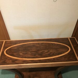
I have been using a router circle jig to attempt elliptical inlays. The kerf created for the inlay to go into is fine, uniform width and depth within 0.010” variance max but the elliptical inlay strips I cut out all show significant width variations at the transitions from the major to the minor axes or where the curvature is maximum. My inlays can vary from 0.750 down to 0.650” which obviously looks terrible in a uniformly 0.750” kerf.
Anyone with any experience or ideas?
I know a pattern/template with various size router guides might be my next step.
attached is a top with inlay that took me 30+ hrs. There must have a better way


Replies
I have never done this so treat as speculative - yours looks great!
Often I have seen this done with multiple pieces of veneer where the oval is wide. This leads to an attractive striated effect.
Stringing is not so hard as thin strips bend easily but consistently cutting a precise match in a solid piece is very hard, especially as it might move somewhat after cutting.
If this were my project, I would try to cut the inlay piece using templates.
Cut an oval slot in MDF as a template - before doing this, mark many straight lines on the board to help alignment later. Use this and a pattern bit to cut an exact copy. Set the outer part of one aside to be a router template to use on your table top.
Remove the width of your pattern bit from the inside and the outside of each pattern using an appropriate rabbet bit. Use the pattern bit to cut the inside and outside profiles of the inlay piece.
Error may occur if there is inaccurate router alignment or flexing of the template.
Or use a laser cutter. This is what laser cutters are for!
Thank you for your thoughts. I was thinking about using templates.
I was hoping to get the 2 axis router jig to work as it would allow me to make a variety of different size inlays. However I thought pattern/template based might be a better option although it would require individual templates for individual size inlays and storing them could become an issue
Using a circle cutting jig to cut two ellipses with even distance all around would require advanced trigonometry to figure out or a lot of trial and error. I would start by setting the longer and shorter axis 3/4 inch lesser than the outer edge. Is that what you did ? But then, I just taught that the diameter of the cutter has an impact so if using a 1/2 inch cutter, the outside of the ellipse has to be 1/2 inch larger and the inside 1/2 inch smaller so 1 3/4 /2 (7/8) difference between the shorter and longer axis.
I cut the inner and outer edges of the inlays adjusting the major and minor axes as needed to get a 3/4” wide inlay multiple times with 1/4, 1/2 & 3/4” bits and always got same results. Inlay was between .740-.750” at centers of major and minor axes on all sides which fit nicely or with a little hand sanding into the elliptical kerf but at curves out where major transitions to minor axis width would be .650-.715”. I got my best result when I set jig to give a .825” wide strip which resulted in ~ .750” wide transition areas and then used a spindle sander to get the oversized areas down to ~ .750”. This approach was time consuming but that is how I completed the table shown in my original post. Just looking for a better way
We are tempted to think it is the limitations of the jig not to be able to reproduce perfect ellipses between the transition points but then you would expect the groove to also be uneven. Could it be that the wood is deflected when cutting the second Pass of the ellipse? One way to find out would be to put a pencil in the jig and trace the outer and inner ellipses and see if the error repeats.
Groove is cut with 3/4” router bit and is uniformly 0.750” wide.
I will try putting a pencil in the router collet and trace the outer and inner edges as well as the center of the elliptical inlay and see if maintains the proper width/dimensions. I will post results
That explains the consistency of the groove width and you will need a similar method to get the inlay width . This problem is as old as the time woodworkers, builders and architects, tried to make ellipses of equal thickness and comes from the fact that if you draw a parallel ellipse, it is no longer an ellipse. I had that taught by looking at pictures of concentric ellipses and my reasoning that the smallest should be a point, representing the top of the cone. An ellipse is the 2D shape of cone cut by a plane. If we remove 3/4 inches from both axis we end up having the shorter axis become zero before the long one and end up with a straight line, not a point. One needs to think about the frame maker making an oval frame for a mirror or painting or the builder of an arch trying to follow an ellipse with materials of even thickness to see that this is an age old problem that often was solved by making an oval shape from two arc of circle joined by a transition, this was called a basket handle arch.
This recent article might help with the templates and method:
https://www.finewoodworking.com/2022/06/27/curved-solid-wood-edging
Using this principle, one would cut the groove with the 3/4 inch bit and use the same set-up to cut a template that would match the inside ellipse. Using a guide bushing that has a 3/4 offset between its outer edge and the bit, for example a 2 inches outer diameter and a 1/2 inch bit this would be used to cut the outer edge of the inlay. Then the template could be cut back 1/2 inch using the rabbet technique and a straight 1/2 trim bit with a 1/2 inch upper bearing used to cut the inside. The 2 inches guide bushing could be made with a custom made washer that fits over a standard brass guide bushing.
In the process of getting various custom sized guide bushings made to do what gulfstar suggests in post #9. If that fails will look at mj#8 suggested article. I will have to think about Gulfstar #7 concepts. At first read they make sense and could very well explain my problems of trying to use sliding 2 point elliptical jig to make inlay.
Thank you both for suggestions.
Will post after my next attempts. Will be traveling for awhile.
The router bit travels farther on the outside of the curve than on the inside. What you need is a router bit with a differential!
Or ...maybe one of those two part inlay router guide bearings that uses a spiral bit. Make a good pattern ,1/4" thick, the inside and outside all one piece..or have one cnced...oooh and out of aluminum! Spiffy! but it will be necessary to have points that hold the inside and the outside together ( but not attached at the tight curves ) and you will have to cut those sections out by hand. I think those things have a 1/4" set back so your pattern would be 1/2" bigger ( wider) than your desired width.
“[Deleted]”
Success with templates and custom made different size router bushings.
“[Deleted]”
“[Deleted]”
This forum post is now archived. Commenting has been disabled