I need to find two angles – see photos. I more or less figured it out by trial and error, but it’s not exact and I’d like to see the math to actually figure them out
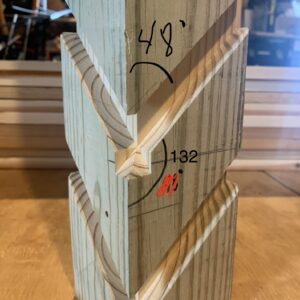
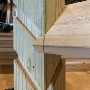
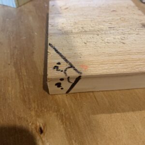
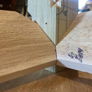
Situation (easier to just see the photos) – I have two 1x6s dadoed on either side of a 4×4 coming down at 48degrees and meeting at the edge. I need to figure out the angles to cut the 1x6s so they meet flush at the edge. The last picture is by trial and error but it’s not a perfect enough fit yet. Thank you.



Replies
With no hope of doing the math...
If you are still set up to cut the dados you could cut a set down low on another piece of post stock and screw it point-on to the blade on a sled for the tablesaw. From there it's just grip it and rip it.
You may want to measure the angles with a protractor to check my logic but this is a compound angle made by turning the miter saw to 45 degrees and tilting the head by 48 degrees from vertical...
That’s what I initially thought, but cutting at those angles doesn’t come close to a tight miter. The actual results I got by trial and later verifying with protractor are around 63
degrees for the tilt and 53 for the miter angle.
Just thinking of my chop saw, could I cut the other side? My saw only tilts one way. In my brain these are a R and L side Would leaving the blade at 48* tilt and swinging to the opposing 45 give me the other side? I think I'm going to have to try this.
I can tilt my saw in both directions so I just need to tilt and swing it in a mirror position for each board on left and right. My head hurts trying to think how to tilt and rotate to do both boards with single tilt saw lol but it should be possible
Also, I can tell you that after getting pretty close with trial and error and later verifying the resulting angles with a digital protractor, none of the results are anywhere near 45 or 48 or reverse of those on a 180 scale, which has me now obsessed with trying to figure this out lol.
It looks like you're pretty spot on with the one you made. I'm not sure you can do much better, straight off the saw. If it needs fine tuning, use a plane or chisel.
Thank you! Yeah, I think for this outdoor project I will just stick with what I got by trial, though I’m now kinda obsessed trying to visualize this in my head and see how in the hell the resulting angles that fit turned out to be the actual answers.
It's a first year engineering problem. It would not be done with math but (originally) through drafting very accurately and measuring with a protractor. The course would be called "Descriptive Geometry".
Let me provide an analogy. One can cut crown moulding in a jig, upside down and backward. That is the easy way. The other way is to lay on its back and make the mitre and bevel cuts. Those angles would be 33.9 for the bevel and 31.6 for the mitre (although those angles are specific to a spring angle of 45 degrees and 90 degree inside or outside corners). Those angles were calculated using "descriptive geometry".
The drafting technique involves taking various successive views until one has a drawing of the "true angle" of intersection between two planes. Where those two planes intersect would appear as a point.
You have two boards that meet and you would take a view sighting down the intersection (so that the intersection line appears as a point.)
I taught the course for 25 years, originally using paper and pencil on drafting boards, later, the "concept" with AutoCAD. Much easier with AutoCAD by simply rotating the view around to see the correct angle, true lengths, true shapes, etc. One 3D shape could give one all the info that originally required many views. (That's why I used the word "concept". Only the concept was required.)
Try it in SketchUp. You have a model. Lift it up and look at it. Rotate it around until you see the correct angle. (That's the "concept.") That is how you want to rotate a 3D model in SketchUp.
Sorry, I'm not going to do it for you. LOL.
Thank you for such informed reply! I basically did the multiple drafts AutoCAD method in real life lol by repeatedly cutting, adjusting, and fitting to get it close enough. Going to try sketchup per your suggestion.
It just seems to me like there has to be a way by inverse trig functions to solve this without resorting to multiple drafts if doing it on paper.
Yes, it would be possible but the math would be much, much more difficult. (The multiple views are actually not too difficult. It's only 1st year engineering.)
Found a nifty online compound angle calculator and for my case it gave me 28.2 for blade tilt and 36.6 for miter angle. Through trial and error I had arrived at 26.5 tilt and 36 for miter. Not too bad, hehe. Being a nerd, I would love to see the math behind those calculations, though.
Two pieces at 90 degrees meeting symmetrically have to be cut at 45 degrees. ( the long line in your picture)
The other angle is the complement of the 132 degrees or 48 degrees. This is the short line in your picture. That is straight geometry.
You might want to check your protractor and insure it is zeroed properly. It is difficult to mark the 48 degree line. Easier to do if you put blade of ruler against the upright and mark the board while it is in position and then set your protractor to match that angle.
Those angles will not work because the 1x6 itself is angled to begin with. The compound angle i’m after is sort of like the angles you see marked on your miter saw when used to cut crown molding on the flat - 31.6mitre and 33.9bevel as was mentioned by Suburbanguy above. Using those “weird” sounding angles together will let your crown molding come together at 90 degrees in corner perfectly. You cannot just lay the molding flat and set both your miter and bevel at 45 - it won’t work.
“[Deleted]”
I'm not a finish carpenter. There are ways that things are done in the field and ways that things are done and put on a drawing "for the shop" without the aid of a model. I know the second technique, but I'm willing to give you my thoughts on the first.
With the model that you've created, place a sliding bevel on one of the sloping boards. Push it up against the 4x4 and the other part of the bevel up against the other (adjacent) side of the 4x4. Measure that angle of the sliding bevel. It will be less than 90 degrees, of course. Divide that angle in half. That will be the one angle required. (In my mind that should be the mitre.)
Take the sliding bevel and put it on one of the boards and pushed up against the 4x4. With the other part of the bevel, align it with the edge of the 4x4. I believe that that will give you the second angle, the bevel, for setting your saw.
Yes! That’s how I started the first cut for my trial run. I found an online compound angle calculator just now - pretty proud of myself: I was only 1.7 degrees off on my bevel and 0.6 degrees off on the mitre. Not sure why I didn’t think to google that calculator to begin with.
My head hurts. I would have built the sled and been done in 20 min without knowing any of the numbers. ...but I am still going to try it with the single tilt saw.
It could not be simple, but internet has a formula and a calculator for it, comes up with :
A = 90 Corner angle
B = 42 Tilt angle
X = 36,62 Crosscut Angle Setting
Y = 28,24 Blade Tilt Angle Setting
I used 42 degrees since it is the complement of 48 and it is measured from the horizontal plane. The formulae is :
X = arctan(cos(B) * tan(A/2))
Y = arcsin(sin(B) * sin(A/2))
But the downloadable excel file is available at : https://www.woodcentral.com/bparticles/miter_formula.shtml
Thank you! I didn’t think to google these calculators earlier today but since stumbling on them I’ve been playing with all sorts of different compound angle combos like various pyramids, frustrums, and many sided polyhedrals, etc. kinda making me want to build some of those things.
This forum post is now archived. Commenting has been disabled