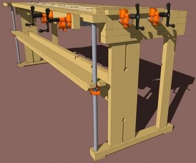
The SketchUp plan for John White's New-Fangled Workbench (FWW #139) is now available in the Fine Woodworking Plan Store.
Editor’s Note: The SketchUp plan for John White’s New-Fangled Workbench (FWW #139) is now available in the plan store so we resurrected this blog post from Jan. 08 with details on how Dave Richards made the drawing.
I’ve been thinking it is time to have a real workbench in my shop. Choosing the right bench design seems to be more difficult than picking the right tablesaw or handplane though. In an effort to help with my decision process I’ve been drawing different benches using SketchUp. I think this is helpful because it lets me look at each bench from various angles. By the time I’ve completed a bench model, I have a pretty good idea of how things go together. I also find as I’m drawing I end up working out an efficient method of machining the lumber so I can avoid having to duplicate setups where possible.
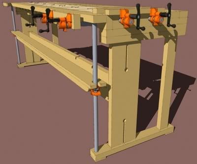
Last weekend I decided to take another look at John White’s New-Fangled Workbench (FWW #139) or the “Six Clamp Bench”, as it has recently been dubbed. John designed it to be quite versatile as well as simple and inexpensive to build.
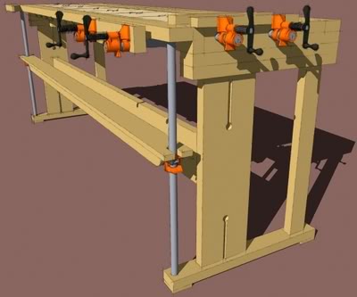
Drawing the bench itself is pretty straightforward. The article and accompanying drawings give few dimensions. Still it’s fairly easy to start with those and build from there. I started with a few guide lines to set out the over all dimensions. Then I drew one of the horizontal boards on for the top. This board was made into a component and copied (Ctrl+Move). Many of the other boards in the bench are modifications of that first one. The Make Unique command and the “Board Stretcher” (Push/Pull) handle most of that modification. There are only 22 different components in the bench itself.
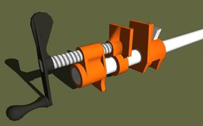
After I completed the bench and the pipes I needed some clamps. Time for a new drawing. I drew the clamp as a separate model and saved it in a component library. I added it to the bench model later.
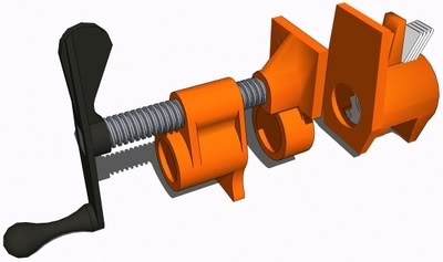
Now, setting out to model something like a pipe clamp awakens the over-modeler in me. It is very tempting to model every last detail just because it can be done. It’s important to consider just how much value high levels of detail actually add to the overall model. Is it worth the time to add fine detail to the model? For this clamp, I wanted something a bit more detailed than simple blocks but I didn’t want a component that was so large that it would bog down the bench model when I added it. I could have sketched it in a sort of free hand matter but I find it easier to take measurements and draw to scale. Since this clamp has to interact with the bench model, it is easier to work with a properly scaled component.
There are a number of areas in this clamp that invite over modeling. If you look closely at one of these clamps you’ll see there is a large number of curves. If you add all the filleted areas, the potential number of entities–edges and faces–could skyrocket. As I worked I made decisions about the number of line segments used for the various circles and arcs in the model. I was looking for a balance between smoothness and minimalism. The paddle end of the crank is an area that shows where I reduced the segment count perhaps a bit too much. This didn’t concern me much and from a distance, it isn’t very noticeable.
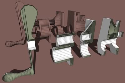
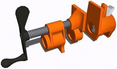
I broke each of the parts down into sections to make it easier to draw. Then I brought those sections together and used Intersect to joint them. After I had a part of the clamp drawn, I split in half down the centerline. As I’ve shown in several other blog entries, I split the part in half and made it into a component. The component was copied and mirrored to make the opposing half and these halves were joined. the faces in the seam were deleted and the seam edges were hidden. The two components are made into a nested component so they can be handled as a unit for moving.
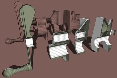
Rather than drawing in the fillets, I used Soften (Ctrl+Eraser) or Hide (Shift+Eraser) to insinuate that those edges are not sharp. The next image shows the components I made to make the clamp. In this view I have turned on hidden geometry. The back faces are shown in green. Click on the image for a larger version.
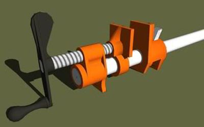
Originally I used a texture in the Metal library called Metal_Aluminum_Corrugated to create a fairly convincing thread appearance. A texture is a good alternative to modeling small detail because it is faster to do and it usually has less of an effect on file size. Note that the size of the image file does impact the size of the SketchUp file.
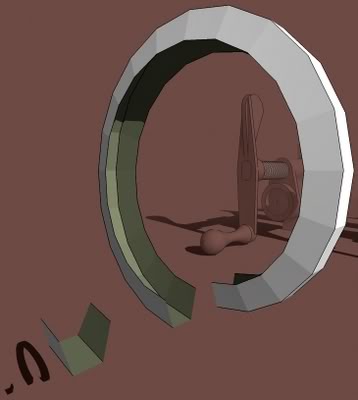
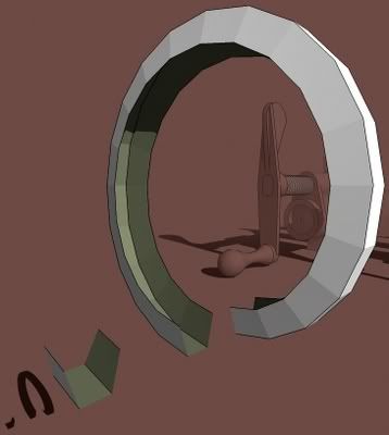
I showed this drawing to some friends. One of them challenged me to add the Acme threads. Little did he know I had already modeled an Acme threaded screw. All I needed to do was scale that component and add it to the model. This component was only 20 Kb because of the way it was drawn. The threads consist of a bunch of instances of a single component. You can see that component in the lower left corner of the next image. This component was copied around the ring to create one trun of the thread. This single turn was made into a component which can be copied as many times as needed to get the desired length of the threads. The center of the screw is simply a cylinder which can be set to length with Push/Pull.
When I got finished with the clamp model I was pleased to see that the file size was only 139 Kb. This is a very manageable file size for a component. The entire bench drawing with the pipe clamps included is 364 Kb. Out of curiosity I exploded all the components in the clamp model and saved it. With no components in the model, the file size ends up at 1016 Kb–Over a meg! That makes a pretty fat component considering how much it adds to the bench model.
The upshot of all this is that with a bit of thought, it is possible to make models with reasonable level of detail while keeping file size manageable and it isn’t at all difficult to do.
As always, if you have questions, please feel free to ask.
Dave Richards
GET THE FULL-SIZE PLANS
SketchUp-drawn plans, a cutlist and the SketchUp model for this project are available in the Fine Woodworking store.
BUY NOW



Comments
Dave- I am new to Sketch Up and serious woodworking and would like to build White's NF workbench. I've bought the Sketch Up plans and read some of the past postings and have a couple of questions.
Black iron pipe is shown as 3/4 inch in diameter in Sketch Up & on the .pdf drawings. John White answered a question from a "Swede"(?)some time ago,indicating that he used 1/2 inch and gave the Pony Clamp model number that fits 1/2 inch pipe. Pros & cons?
Your Sketch Up drawing indicates that the 1/4 inch hard board on the planing beam is 4 inches wide but the .pdf file (of White's article?) shows it as 5 inches wide.
Any idea why White used copper caps for the ends of the tail vise pipes? I'm having difficulty finding ones that fit. Any disadvantage to just using an iron end cap?
Is there an easier way to get Sketch Up to show the dimensions other than using the dimension tool on a component?
Appreciate the work you've done.
Oliver
Oliver, pipe dimensions are given as the inside diameter of the pipe. 1/2" iron pipe has a nominal outside diameter of .840 or about 27/32.
As to why copper caps? I don't know. Perhaps he had them on hand or maybe they were cheaper than iron caps especially if the pipe isn't threaded at that end as he might have had to pay to have the ends threaded.
I see in a photograph of the bench that the hardboard cover on the planing beam does appear to be as wide as the planing beam itself. (5") It probably wouldn't make any difference if you make it 4" wide or the full width since that extra inch isn't really usable anyway.
As to getting SketchUp to show dimensions, they aren't there unless you put them in. You could generate a report or run a cutlist and get the dimensions in tabular form but there's no automatic way to have the dimensions show in the drawing.
Dave
Dave - Thanks for the responses. Note however, that the "cut-list" (which I take to the store) in the .pdf with the Sketch Up drawing lists all the (black) iron pipe & clamp assemblies as 3/4 inch which has an outside diameter of a little over 1 inch, and would not slide through the 7/8 inch washers for the Front Vise.
If you have a way to contact John White, it would be interesting to know if he had any problem with excess flexing of the 1/2 inch pipe when clamping a 7 foot workpiece and if he feels there is any advantage to using the larger nominal 3/4 inch pipe. Otherwise, it is cheaper to use the 1/2 inch pipe & clamps.
Thanks again,
Oliver
Oliver, would you please contact me via e-mail? drkr4109 at gmail dot com.
Thank you.
Dave
Log in or create an account to post a comment.
Sign up Log in