Little Red Thickness Guage
The thin and the thick of it.
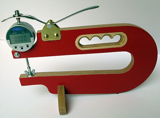
I wanted a thickness gauge with a digital display, adjustable lower contact point and the main contact point positioned vertically in the middle of the throat.
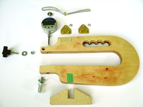
I started by purchasing a fairly low cost digital indicator, settled on a piece of scrap ¾” Baltic Birch ply from a building mold for the body, figured out how to deal with the lower contact point by turning a threaded insert and how I would keep the indicator securely attached to the body. I proceeded to fashion a fairly typical elongated “C” shaped body, laid out the holes for the indicator and lower contact point, drilled the holes while the blank was still squared up (just cut the two ninety degree cut outs for the upper and lower arms then drill) and cut the body out. A foot was fashioned from ply and in a few hours I had a workable prototype with one exception. I had no easy way to lift the rod of the indicator. I had another problem; the indicator has a dust seal type cap on the rod with nowhere to attach a lifting mechanism. So I went off on a long search of how to lift this rod. I looked at dozens of pictures of DIY and manufactured gauges and most had an arm that attached to a pin at either the top or bottom of the rod. But my indicator had no pin and after looking at modifying a screw on “point”, I decided that I needed another method. I came across some indicators that had a lifting arm accessory that attached directly to the case of the indicator. This would have worked fine but alas, my indicator did not support such an add-on. It did however provide the idea for the eventual design.
The prototype deflected more than I wanted (the arms were not tall enough) just by touching the arms so they would need to be beefed up. I wanted more vertical room at the back of the slot (to allow me keep the reading as close to perpendicular to the surface as possible) so I angled the slope of the slot down a bit. I originally used a blind nut to clamp the indicator in place but there was not enough plywood at the end of the arms to keep them from splitting at the edge. I chose to keep the tip dimension the same but inlet a regular nut instead. The lower contact point was turned from a regular ¼ -20 bolt. (The head of the bolt is now the contact point) A wing nut allows the bolt to be locked in place. It is threaded into an aluminum insert which is a press fit into the arm. Still no love with the lifting arm but I needed it next so now was the time for all good brains to come to the aid of their owner.
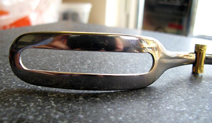
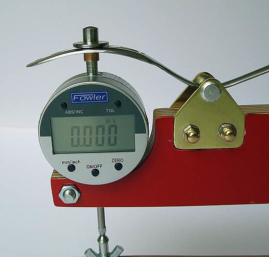
Using pictures from the web of indicators with a small lifting arm I enlarged the image to full size and made a couple of measurements. I took the dust seal cap off the rod and removed the chrome plating from the bottom half inch (sanded with 220 grit). I then chucked a washer in the lathe and bored the hole to fit the cap. The washer was then soldered to the cap. (The hole was sized for a press fit) I looked for material to make a lifting arm and remembered seeing a picture with a dinner fork being used with some of the tines removed and this led me to using a large soup spoon. I was able to find a package of two very heavy stainless steel “Betty Crocker” soup spoons at the dollar store. I layed out and cut a slot in the spoon using a dremel tool and cut off wheels and then using a small scrap block of wood I played around with the location of where the pivot point needed to be to ensure smooth lifting of the rod. The spoon was bent to accommodate the pivot point and ensure that the handle of the spoon would not come into contact with the top of the body when deflected. Who knew heavy stainless steel spoons were SOOOOOOOO!!!! Strong J
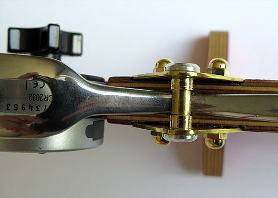
Now I needed a pivot mechanism and this kind of drew itself. The pivot would have to be round and the handle of the spoon would have pass through the pivot. I chose brass tubing for the pivot axle and took two pieces of telescoping tube and soldered them together one inside the other for greater strength. I now calculated the dimensions of the side bearing plates and soldered two pieces of 1/16” brass plate together by tinning both and then sweating them together. I squared one edge with files then laid out and created a perpendicular to give me two reference surfaces. The resulting piece was coated with tool makers ink (black marker is just as good) and using a surface plate (any flat surface would do) and height gauge (a nail on a stick?) laid out a center line and height lines for the pivot point and the acorn nuts (entirely decorative and not required). Joining two pieces together allows you to make two identical pieces at once. After everything was laid out, drilled, threaded, shaped and sanded I again heated them up and separated them.
Once I had these pieces I was able to calculate the hole diameter for the pivot bearing using the next size up of brass tube. I jigged up the two side pieces with the brass tube between them and the edges set against a “T square” to maintain concentric alignment of the bearing centers. I used the two factory ends of the tube as the inside ends (to avoid crushing the tube with a tubing cutter and maintain a perfectly plum edge) then silver soldered the plates to the tube with the bearing portions projecting outwards from the plates and the part to be cut off acting as a support between the two plates. The plates were cut free with a jewelers saw then the inboard ends were made flush with files.
The pivot axle was laid out to be just a few thou shy of the distance between the outside dimension of the mounted side plates. I laid out a center line on the double thickness tubing leaving about 1/8” extra to ensure the tubing would not crush as I worked on it. (I ground it off after the pivot axle was finished) I then drilled two holes on the center line such that the hole diameter was the same as the thickness of the spoon in the way of the pivot point and spaced such that the outer dimension of the distance between the two holes was just a few thou shy of the distance between the left bearing tube inside face and the opposite side plate. I then used a jeweler’s saw to join the two holes and finished the slot with small needle files. The pivot axle was cut to length (with the closed end ground off until the slot was open and able to receive the spoon handle) and carefully de-burred. I now had all the working parts for the pivot but wanted to dress it up a bit. I tuned two aluminum end caps which are held in position with epoxy. The acorn nuts are threaded onto brass bolts, soldered together then cut free of the bolt head. Holes were drilled and threaded in the plates and the nuts were tightened in place then soldered to the plate. The projecting portion was cut off the back side and filed flat.
I had already laid out the position for the side plates on the upper arm and let them into the plywood. The spoon handle is epoxied (industrial epoxy with micro balloons to make a paste) into the slot in the pivot axle. First a piece of tubing the same diameter as the inner pivot tube is sharpened on the inside and then small 1/16” balsa plugs were made to act as glue stops. The first plug was slid into place in the non slotted end (using a drill bit of the same diameter) up to the edge of the slot and can be seen in the photo. (This will keep the epoxy out of the tube) The slot was filled with epoxy and the spoon was slid in place. (Don’t forget to mask off the rest of the spoon first!)More epoxy was applied to the slotted end and the second plug was inserted tightly right up to the edge of the spoon. This now ensured that the epoxy was forming a dowel around the spoon handle and that the handle could not move back and forth within the slot or side to side. (It sounds complex but really just took a couple of minutes) The spoon was now mounted to the plates which had been masking taped in place and the indicator installed in place. The dust cap with the washer was screwed in place, the lever arm checked for alignment and the whole thing was allowed to set for a day (don’t touch it again till it sets!)
The body of the gauge was laid out with a 2 5/8” tall upper and lower arm, (they taper a bit towards the mouth) and a 1 1/8” radius at the rear. The throat is 9 3/8” from the contact point to the end of the slot. The body stands 6 1/8” tall. A handle was laid out by drilling a chain of four evenly spaced ¾” holes with a hole saw and then filed to shape. (put on some tunes and get comfortable as this takes a bit of time as did grinding the grooves off the bottom of the spoon and polishing it all back to a shiny surface)
I hope this helps someone make their own gauge or tackle something that seems complex but really just requires working through a bunch of small issues.
Questions are always welcome.
Kim.
Normal 0 false false false EN-CA X-NONE X-NONE MicrosoftInternetExplorer4 /* Style Definitions */ table.MsoNormalTable {mso-style-name:”Table Normal”; mso-tstyle-rowband-size:0; mso-tstyle-colband-size:0; mso-style-noshow:yes; mso-style-priority:99; mso-style-qformat:yes; mso-style-parent:””; mso-padding-alt:0cm 5.4pt 0cm 5.4pt; mso-para-margin:0cm; mso-para-margin-bottom:.0001pt; mso-pagination:widow-orphan; font-size:11.0pt; font-family:”Calibri”,”sans-serif”; mso-ascii-font-family:Calibri; mso-ascii-theme-font:minor-latin; mso-fareast-font-family:”Times New Roman”; mso-fareast-theme-font:minor-fareast; mso-hansi-font-family:Calibri; mso-hansi-theme-font:minor-latin; mso-bidi-font-family:”Times New Roman”; mso-bidi-theme-font:minor-bidi;}


Log in or create an account to post a comment.
Sign up Log in