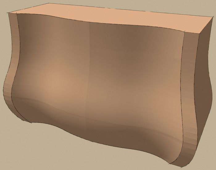
I have a bunch of great woodworking friends who use SketchUp. They are always coming up with challenging projects. One of my friends asked me about how to go about drawing a chest like the one featured in an article called Boston Bombé Chest by Lance Patterson in FWW#45. This would be a big challenge but, thanks to some useful plugins, it isn’t too bad. In this installment, we’ll work on the front surface of the chest.
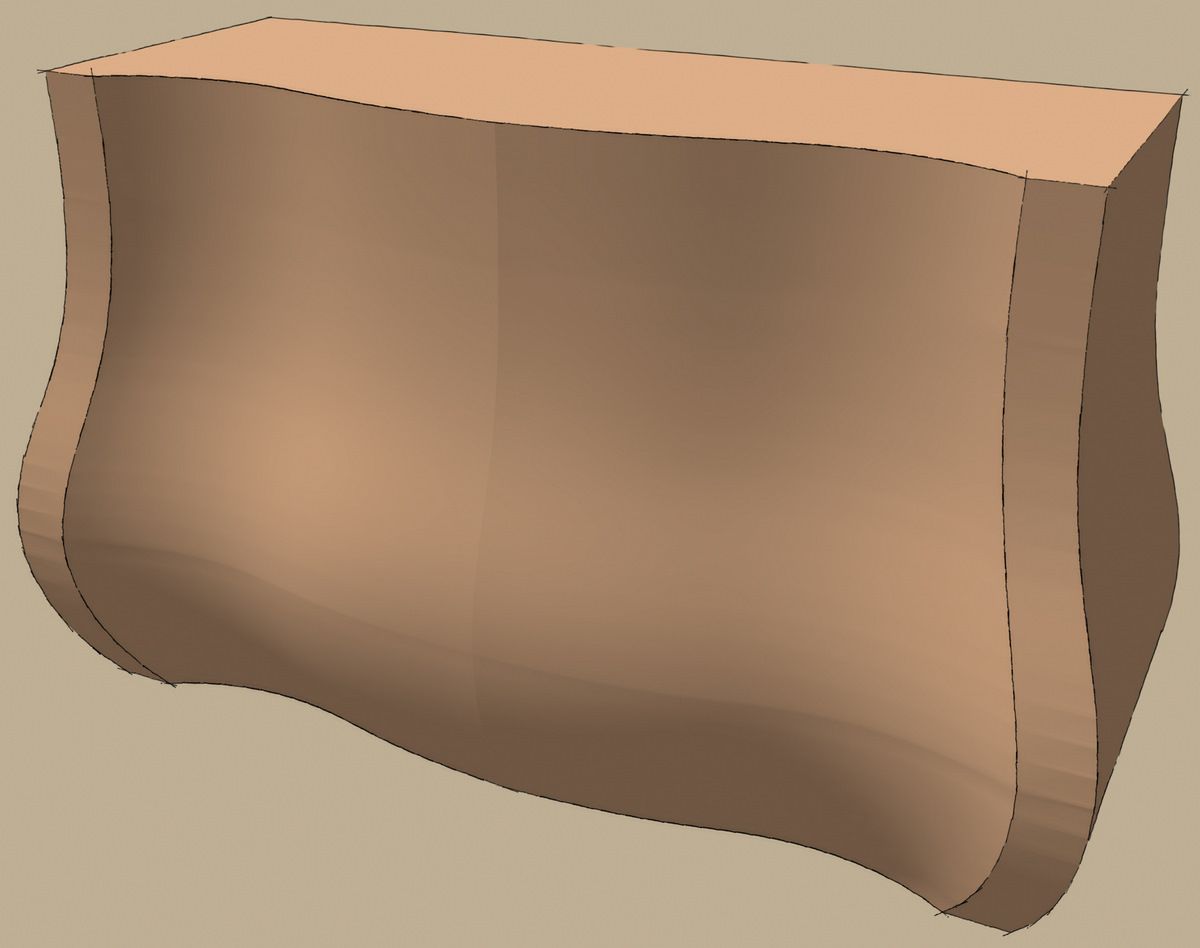
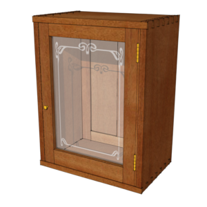
I haven’t drawn the whole chest yet. I did the image in brown, above, as a proof of concept sort of thing and I’ve worked out the method for drawing the drawers and rails. You’ll get to see the rest of it take shape almost as I do.
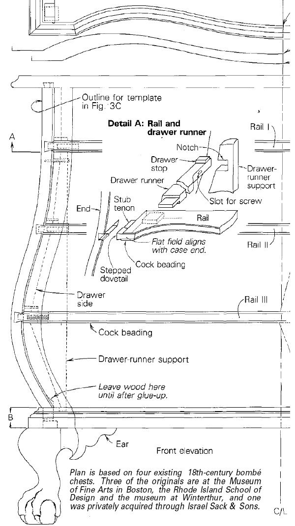
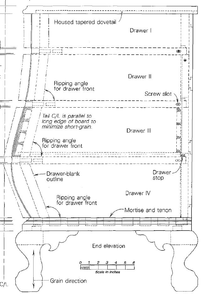
For this example I am working right from the drawings in the article. I made screen shots and imported them into SketchUp. Tim and I have covered this operation before so I won’t bore you with that here. These are my starting images.
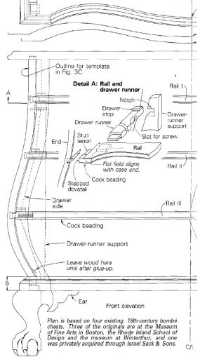
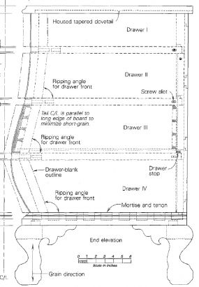
From these images I was able to pick out and trace the curves I needed for the front of the chest. Since the chest is symmetrical left to right, I’m only drawing one half. I’ll copy and flip that half later. Before starting to draw, I scaled both images so they match and I decided to work at a scale factor of 100. The right hand image has a scale between the feet so I used that as my reference for scaling. I like to use the yellow Tape Measure tool to do the scaling for something like this. I drew a line the length of the scale in the right hand image. Then I measured it with the Tape making sure to click on both ends. I typed 600 and hit Enter. SketchUp asks if you want to resize the model and we answer, “Yes”.
Then to get the left hand image to the same scale, I measured the height of the case in the right hand image. That worked out to 2275 inches. I exploded the left hand image and immediately made it a component. I opened the component for editing and drew a line between the top and bottom of the case. Then I measured it with the Tape and entered 2275, Enter. this time, instead of scaling the entire model, SketchUp scales only the active component.
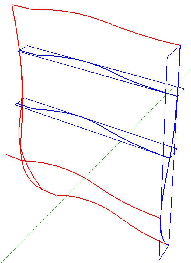
With those images scaled, I began drawing my lines. For the sweeps of the rails I drew the straight lines at the left end and used the Bezier tool from the BZ Spline plugin to draw the curves. Before drawing the curves for each sweep I drew a short line segment parallel to the red axis from the centerline toward the left. I do this to ensure that when the half is copied and flipped, the faces adjacent to each other are coplanar. This helps to hide the seam line. I made these lines 2 inches long but as it turned out, I should have made them a bit longer. Probably something closer to 10 inches long would have worked better. I used Weld to weld the curves and straight lines together in anticipation of needing to select them as single entities.
As I completed each sweep and the curves for the front and sides of the case, I made them components. This made it easy to handle them and there’s no worry of breaking one curve if it is allowed to intersect with another. You could use groups here but I chose to use components. I’ll need to explode them in a little bit but I want to have access to them later in case I make a mistake or the computer crashes or something. By making them components rather than groups, they are included in the In Model component library. When I know that I won’t need them anymore, I’ll purge the unused components from the library.
I rotated the rail sweeps and the front curves of the case and moved them into place using the images as references. I’ve shown some of the components selected.
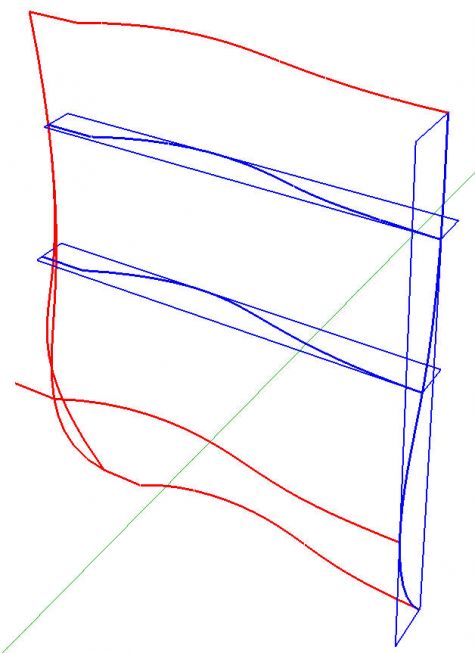
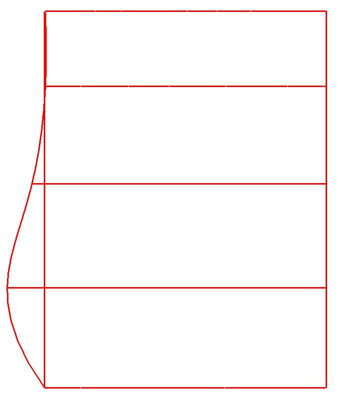
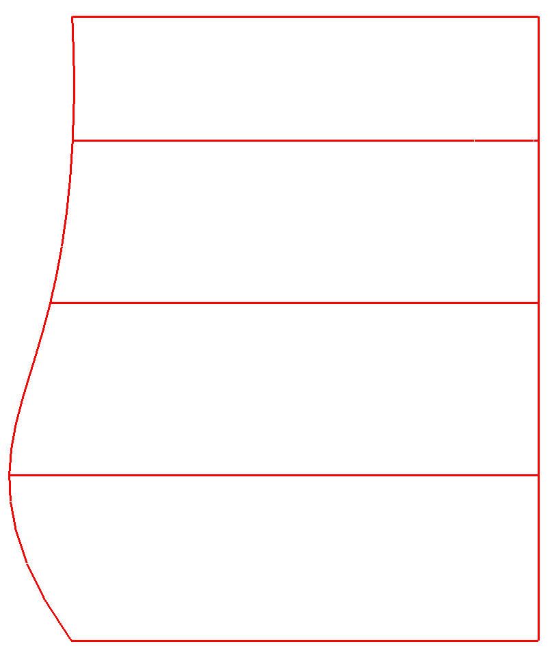
Below is a view from the front with the camera set to Parallel Projection. The vertical line on the left is the front left curve.
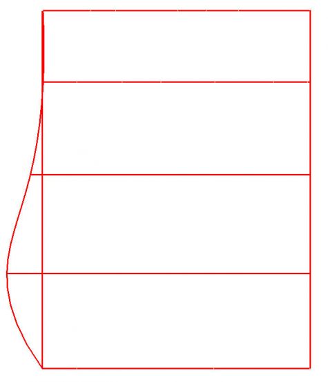
and here is a top view.

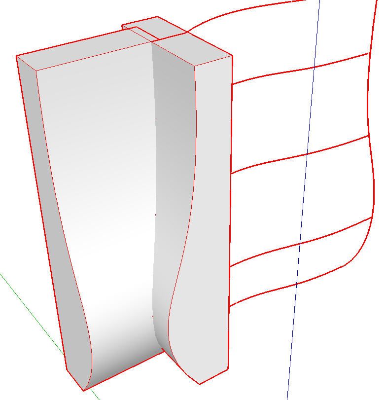
Over on the left there’s actually two curves. the one for the front and the one for the side. What I really need here is the curve where those two shapes intersect. That’s the front left corner of the case. So I opened those components for editing and added some lines to create faces. Then I used Push/Pull to extrude those faces so I have two intersecting shapes. in the image below you can see those shapes but there is no line at their intersection.
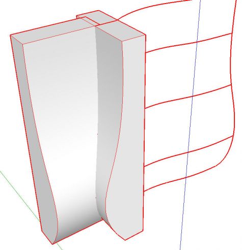
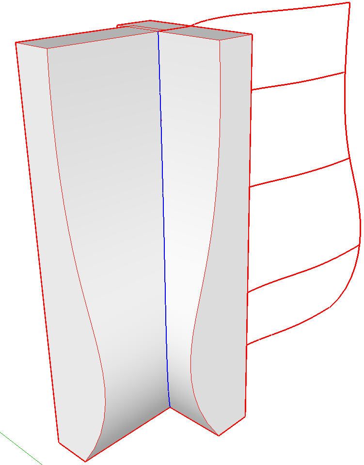
I exploded both components and selected all of their geometry. I right clicked on the selection and chose Intersect Faces>With Selection. This results in the curve highlighted in blue, below.
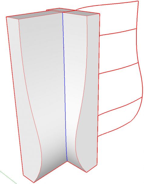
I deleted everything but that curve and then I welded it and made it a component. I spent a little time making sure that the endpoints for the sweeps of the rails met at the corner curve as well as the centerline curve. You can open each sweep component in turn and move end points or the entire curve as needed to make sure they contact the upright curves. They won’t actually intersect at this stage because they are still separate components.
From the front we now have this:
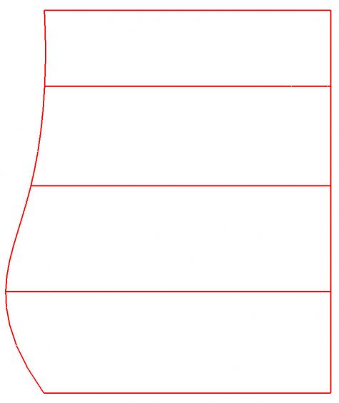
And from the top:

The next step is to explode all of the components. Check to see that the horizontal curves actually intersect the vertical curves. You can do this by clicking on the vertical curves. If you only select those edges that fall between the horizontal curves above and below the cursor, you’ve got the intersections right. If your selection continues beyond a horizontal curve, you’ll need to edit the horizontal curve to make it intersect.
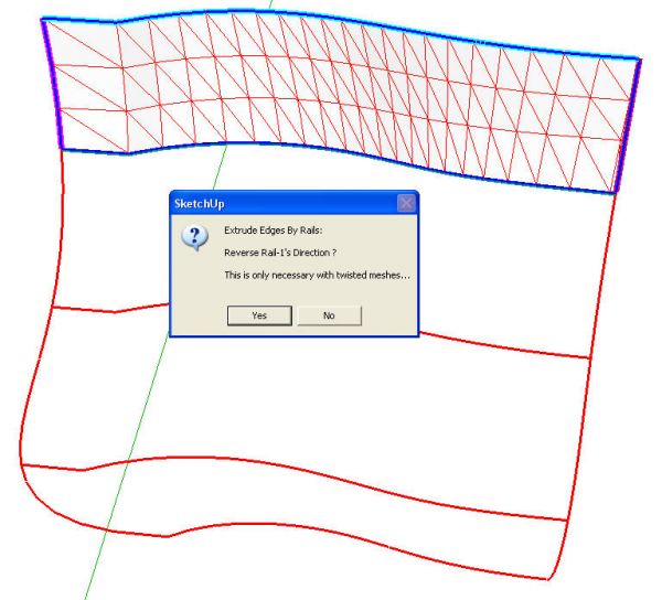
Now it is time to create the surfaces between the curves. This could be done manually by drawing lines between vertices but it would take a long time. I used Extrude Edges by Rails which makes quick work of this part.
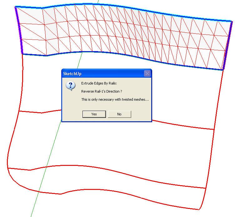
In the next image you can see the first surface has been created. To get this far I selected the Extrude Edges by Rails tool. The directions are to select the first Profile Curve (shown in cyan at the top), then the first Rail Curve (violet, on the left), the second Rail Curve (violet on the right) and finally the Melding Profile Curve (cyan at the bottom). Immediately after selecting the Melding Profile Curve, the surface will be generated and a series of options will pop up. The first one is shown below. In this case the face orientation is correct so the only two options for which I chose ‘Yes’ are deleting coplanar edges and smoothing edges. It actually would have been easier to choose ‘No’ to smoothing the edges, though. I made sure to answer ‘No’ to deleting the original edges because I wasn’t sure I was finished with them.
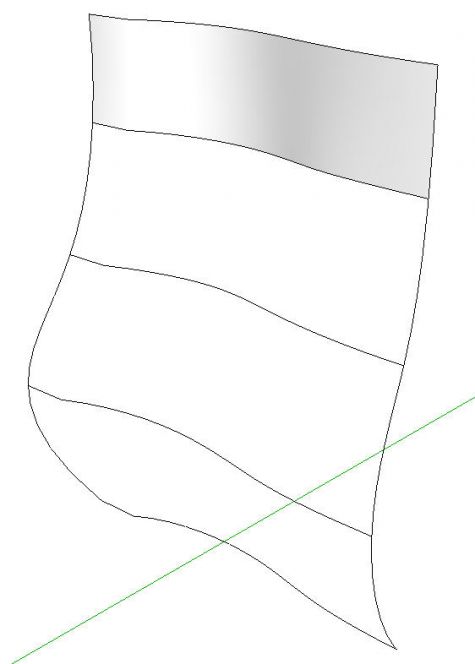
After all those steps we have this:
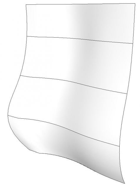
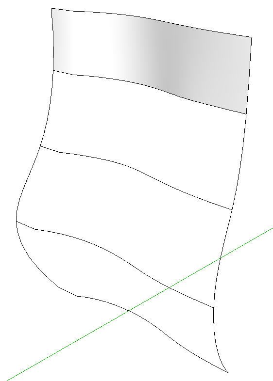
Repeat those steps for the rest of the faces and we end up with the following.
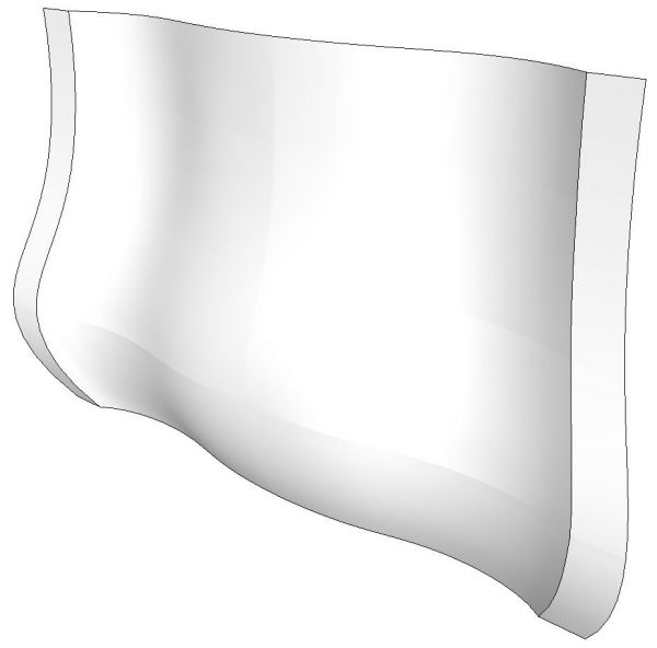
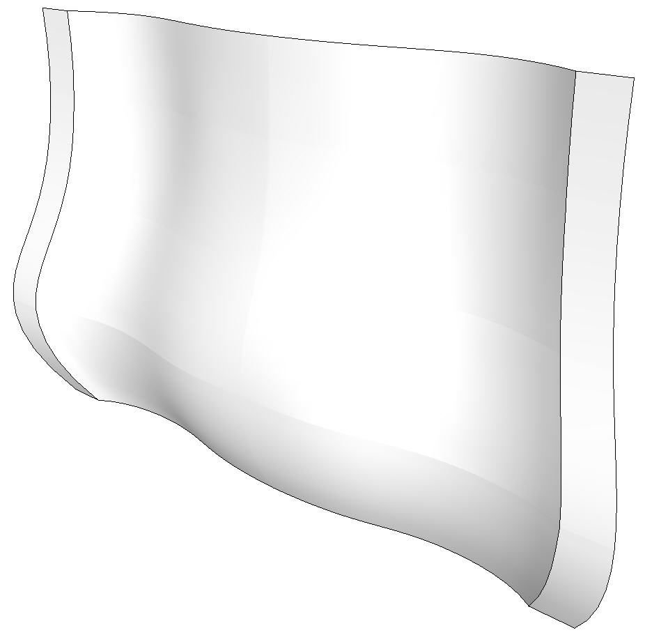
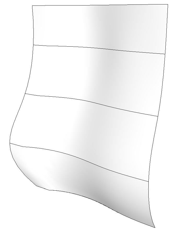
If I hadn’t chosen to smooth edges when creating the surfaces with Extrude Edges by Rails, I would have skipped the next step. I turned on Hidden geometry and then unsoftened the edges between the flat areas on the left and the sepentine curve areas. Instead, I could have selected the faces, right clicked and chosen Soften/Smooth Edges. Either way we end up with the edges as shown in the next image. In this image I’ve also copied and flipped the surfaces to get an idea of what the whole case front looks like.
In the next installment we’ll create the side of the case and get started on making the drawer fronts and rails.
While you may not be interested in drawing a bombe chest, I hope you find something useful in this that you can use in your own drawing.







Comments
I'm the unnamed friend who put Dave (and Tim Killen) up to this. So I probably owe them an apology.
A piece with compound curves--whether it's this bombe chest or something that Michael Fortune might have designed--is probably the biggest challenge in SketchUp. Challenging, but not impossible, as Dave's explanation shows.
When I tried to draw the chest, I created the overall outline in a slightly different way. The curves at the top and bottom of the front are identical. And the bulge in the front is identical to the bulge on the side. So I drew the side component, copied and rotated it, gave each copy some thickness, then intersected them as Dave explained. Then I positioned them and placed the top and bottom curve between them. After I was satisfied that all four pieces were actually joined, I used the Extrude by Rails plug-in, as Dave did, to create the face.
Either way, it works.
You might not like a bombe chest, but I think it makes a great exercise in how to analyze a complex piece of furniture, break it down to its essential elements, and then re-create it.
To David5346, thanks to you and other readers, who bring challenging questions and models. I learned quite a bit from this example. Yes there are multiple ways to tackle the project. And this one requires going beyond Push/Pull, Intersect, and Follow Me.
It's fun and encouraging to see readers stretching skills and taking on challenging work.
Tim
Hi Dave- I'm the first to admit that I'm not very plug-in savvy, but I wonder if, instead of the "extrude by rails" plugin, you could have accomplished the same by using the "skinning by shapes" plugin that you used in the Windsor chair seat demo? I'm trying to keep my learning curve to a manageble radius.
Thanks,
Michael
Michael, I tried using the Curviloft plugin but had no luck getting it to work. I did get some very unusual shapes but nothing that I could use.
Thanks for valuable info? Mike. There is very little data on
making bombe drawings.
However, it is unclear to me how did You make those two strips on the sides of the front? -They are missing on the stages of extrusion but they are shown on the brown completed front
P.S. David, I am very sorry to have called You Mike by mistake.
Unfortunately I do not know how to edit comments here
Still hope You answer my question about those flat side borders on the front. )))
In reply to "user-6893762", the strips on the sides are created during the skinning process with Extrude Edges by Rails. You can see where they are in the plan view of the lines and then in the next screen shot the leftmost triangles are the start of that surface.
They don't show very well in the second to last screen shot because the extension softened the edges. to make them show, I turned on Hidden Geometry (View menu) and then selected those edges. Then I unsoftened them. There are a couple of ways to do that. One would be to set the Soften/Smooth slider all the way to the left. The other would be to untick the boxes for Soft and Smooth in Entity Info.
An alternative would have been to click No when prompted by the extension to soften edges. Then go back and soften the edges you do want to soften leaving those you don't want softened alone. I think the method I used was less work.
I hope that helps.
-Dave
Dave,
Thanks for prompt answer. I really appreciate it.
It takes some thinking activity for me though, since I'm not an expert in al lthose "softening ages" but I'm sure the understanding will come )))
Log in or create an account to post a comment.
Sign up Log in